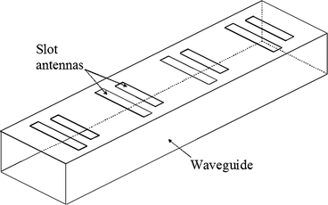
Slot Waveguide Array
Slotted antennas, a complement to dipole antennas, have slots a λ/2 long and a fraction of a wavelength wide. The antenna propagates based on Babinet’s principle of a resonant radiator. The key difference between a dipole and a slotted antenna is the field components are interchanged in orientation. Because of the vertical electric field in horizontal orientation, slot arrays can fit on the surface of moving objects without introducing much aerodynamic drag and wind load. For the same size, slotted waveguide array antennas are more efficient than any other planar antenna. Versatility in slot feeding options, ease of weather-proofing and mechanical stability make slotted antennas well-suited for military and defense applications.
- Waveguide Slot Array Antenna
- Waveguide Array Slot Ku Band Antenna
- Waveguide-slot Array Antenna Designs For Low-average-sidelobe Specifications
- Slot Waveguide Array Programming

Many techniques have been discussed in the literature to enhance the bandwidth of traditional slotted waveguide array antenna. As it has been discussed in the previous section, the use of thin wall waveguides, reduced cross sectional waveguide, wide slots, and modified slot shapes are the reported techniques to improve the bandwidth. A new Computer-Aided Design technique for designing resonant edge-slot waveguide arrays was used to successfuliy design such an X-band radiometer antenna for the NASA Light Rainfall Radiometer (LRR) instrument. Having the ability to rapidly create such an extremely accurate and efficient antenna design without the need to manufacture prototypes. This paper discusses the design, analysis, and development of waveguide-fed planar slot arrays to achieve low-average-sidelobe specifications, as may arise in radiometer applications. Such antennas may be required to meet strict average sidelobe levels in different angular regions, and low average return loss over a specified bandwidth. In addition to Elliott's design technique, we used a. Waveguide Slot Array Simulation seconds The 10-element model is built by using the single slot model and applying a single Copy operation to create the other 9 array elements. The slots are positioned periodically at the points where surface currents would otherwise be longitudinal, at the upper side of the waveguide, one guide-wavelength apart. A circularly polarized crossed slot waveguide antenna array comprising: at least a first pair of waveguides supporting only the TE 10 mode disposed side by side, each of said first pair of waveguides having a first broad wall facing in the same direction, each of said first broad walls having a longitudinal center line;. A first plurality of crossed slots disposed in each of.

For radar and communication systems, Eravant, formerly SAGE Millimeter, has developed the SAW-3533532716-28-L2-WR, a slotted waveguide array antenna operating at 35 GHz with 500 MHz bandwidth. The bandwidth can be increased by increasing the slot width, with cross-polarization increasing as a trade-off. The SAW-3533532716-28-L2-WR slot array supports linear, vertically polarized signals with high aperture efficiency and low VSWR. The antenna has 27 dBi gain with a half-power beamwidth of 16 degrees in the E-plane and 2 degrees in the H-plane. A radome of LEXAN polycarbonate makes the antenna suitable for outdoor applications. Its 1 lb. weight and small size - measuring 11.84 in. x 3.85 in. and just 0.93 in. thick - eases mounting and minimizes the dynamic load to the overall structure. A groove for an O-ring in the standard WR28 waveguide flange (UG-599/U) pressure seals the connecting interface. Integrating the antenna with a T/R diplexer, a dual channel I/Q receiver and an oscillator makes a complete package for many system applications, such as traffic management, law enforcement, communications and military surveillance.

Waveguide Slot Array Antenna
The slot array antennas offered by Eravant span WR90 to WR10 and are designed with MIL-F-3922 designated standard flanges as the microwave connector interface.
Eravant, formerly
SAGE Millimeter
Torrance, Calif.
www.eravant.com

Recent News
News Categories
Slotted waveguide arrays consist of a number of slots cut into the walls of a waveguide forming an array with the slots acting as individual radiating elements.
Waveguide Array Slot Ku Band Antenna
The specific design task here is a 10-element transversal slot array cut into the upper wide side of a WR-51 standard rectangular waveguide. The operating frequency is the center of the K band, 8.5 GHz.
Single slot model requires only 231 unknowns thanks to higher order MoM applied in WIPL-D Pro 3D EM Solver. The array model is built by using the single slot model and applying a single Copy operation to create the other 9 array elements. That model requires only 1149 unknowns. Single slot simulation lasts under a second on a standard desktop PC or any low-end laptop with dual or quad core CPU, while the array simulation lasts only a few seconds.

Waveguide-slot Array Antenna Designs For Low-average-sidelobe Specifications
Section: Arrays & Radomes
Slot Waveguide Array Programming
For full version of the document, please check the following pdf.